 SDrive-MAX is a disk drive/tape recorder emulator for Atari 8-bit computers. It’s open source project based on sdrive-ng ported to Arduino platform. All source code and many usefull informations you can find on a github project page: https://github.com/kbr-net/sdrive-max
1. The basic components
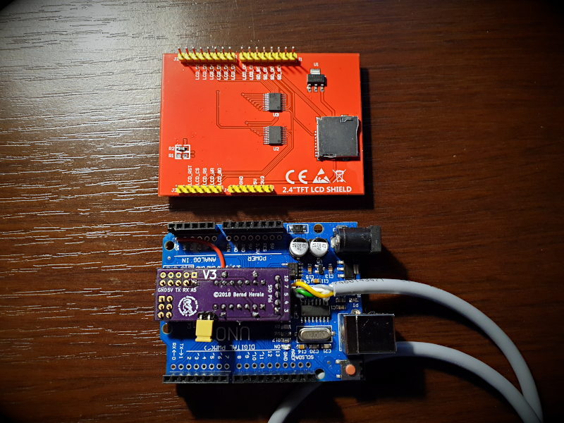
- An Arduino UNO / ATMega 328 development board
- 2,8” TFT Touchscreen with a microSD card slot
- A cable with a SIO plug
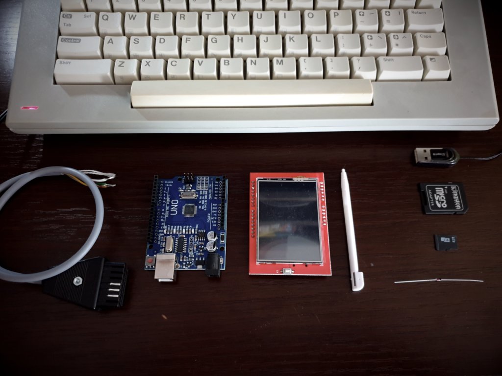
You can buy a board with ATMega 328 microcontroller for about 16-25 PLN on Allegro. A cheap source of Arduino clones could be eBay or AliExpress. Price range between 2,50 to 7 USD. I paid 19.99 PLN (~5.20 $). When buying a set with a power supply or USB cable you will pay a little more, but you probably already have such a cable in your home (eg from the printer). If you have such cable, it can be used with any mobile phone charger with a 5V output voltage.
Another important element is a touch screen with a microSD card slot. It must be so-called ‘shield’ compatible with Arduino Uno R3. It’s best to buy one with the ILI9341 chip. The latest version of the code from GitHub also supports ILI9329, ILI9340, HX8347G, HX8347I controllers. Before you buy, make sure in the specification that the outputs are compatible.
I bought mine on Allegro together with a UNO board (for PLN 32.56 = ~ USD 8.5), so I did not pay for the delivery cost.
The last necessary thing – the cable with the SIO plug. You can have it for free from your old damaged Atari tape recorder, for example. You can get a completely damaged recorder at auctions for the price of scrap with a little luck. Check if the cable has already been cut!
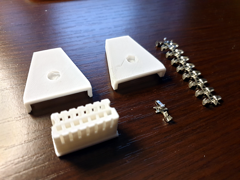 The second option is to make the cable yourself. You need a 5-wire signal cable – about 0.5m should be enough. You can print the plug yourself on a 3D printer. You can find several projects on Thingiverse. However, you will also need contact plates. Printed plugs (ready for assembly) were distributed for free by our friends from Slovakia on the last SillyVenture party, I greet them warmly 🙂 If you don’t have a printer, write to them. The cost of PLA material along with the plates should not exceed $ 1.
Truly recommendable one is an SIO cable available on Lotharek website. It’s an extremely high-quality product at a very affordable price (~ 7.80 USD). I have one myself.
In the original design, there is a 1N4148 diode as an option. It will not be necessary anymore, its role will be taken over by an additional circuit – but more on that later.
2. Programming of the microcontroller
Connect the UNO board to the PC computer with the appropriate USB cable. We do not need to mount anything more for now. You will need:
- Arduino IDE – needed to compile the source code if you want to have the latest version of the firmware from GitHub. It also contains drivers for Windows, so that the system can properly detect the connected USB board;
- avrdude – to program the board, will be used to burn a ready binary file with firmware;
- sdrive-max-v11.zip – ready binary hex files;
Unpack the downloaded zip file. We will get the catalogues from which we choose the one whose name corresponds to the version of our screen driver, in my case it was atmega328-ili9341.
There will be two files inside:
- eeprom_writer.hex
- SDrive.hex
If you are programming under Windows, check in the Device Manager which serial port has been assigned to the device. Use it with the -P parameter. In my case it was COM6.
The entire programming process should be as follows:
E:\atmega328-ili9341>avrdude -carduino -pm328p -P com6 -U flash:w:eeprom_writer.hex

 avrdude: AVR device initialized and ready to accept instructions
 Reading | ################################################## | 100% 0.01s
 avrdude: Device signature = 0x1e950f
 avrdude: NOTE: FLASH memory has been specified, an erase cycle will be performed
          To disable this feature, specify the -D option.
 avrdude: erasing chip
 avrdude: reading input file "eeprom_writer.hex"
 avrdude: input file eeprom_writer.hex auto detected as Intel Hex
 avrdude: writing flash (3484 bytes):
 Writing | ################################################## | 100% 0.65s
 avrdude: 3484 bytes of flash written
 avrdude: verifying flash memory against eeprom_writer.hex:
 avrdude: load data flash data from input file eeprom_writer.hex:
 avrdude: input file eeprom_writer.hex auto detected as Intel Hex
 avrdude: input file eeprom_writer.hex contains 3484 bytes
 avrdude: reading on-chip flash data:
 Reading | ################################################## | 100% 0.51s
 avrdude: verifying …
 avrdude: 3484 bytes of flash verified
 avrdude: safemode: Fuses OK
 avrdude done.  Thank you.

 E:\atmega328-ili9341>avrdude -carduino -pm328p -P com6 -U flash:w:SDrive.hex

 avrdude: AVR device initialized and ready to accept instructions
 Reading | ################################################## | 100% 0.01s
 avrdude: Device signature = 0x1e950f
 avrdude: NOTE: FLASH memory has been specified, an erase cycle will be performed
          To disable this feature, specify the -D option.
 avrdude: erasing chip
 avrdude: reading input file "SDrive.hex"
 avrdude: input file SDrive.hex auto detected as Intel Hex
 avrdude: writing flash (30992 bytes):
 Writing | ################################################## | 100% 5.21s
 avrdude: 30992 bytes of flash written
 avrdude: verifying flash memory against SDrive.hex:
 avrdude: load data flash data from input file SDrive.hex:
 avrdude: input file SDrive.hex auto detected as Intel Hex
 avrdude: input file SDrive.hex contains 30992 bytes
 avrdude: reading on-chip flash data:
 Reading | ################################################## | 100% 4.02s
 avrdude: verifying …
 avrdude: 30992 bytes of flash verified
 avrdude: safemode: Fuses OK
 avrdude done.  Thank you.
Under Linux, the process is similar, but we will check whether the board has been properly detected and under which system device is hidden:
$ sudo su

$ lsusb
Bus 001 Device 009: ID 1a86:7523 QinHeng Electronics HL-340 USB-Serial adapter

$ dmesq | tail
[  521.212625] usb 1-1.4: new full-speed USB device number 9 using ehci-pci
[  521.321533] usb 1-1.4: New USB device found, idVendor=1a86, idProduct=7523
[  521.321536] usb 1-1.4: New USB device strings: Mfr=0, Product=2, SerialNumber=0
[  521.321537] usb 1-1.4: Product: USB2.0-Serial
[  521.321807] ch341 1-1.4:1.0: ch341-uart converter detected
[  521.322485] usb 1-1.4: ch341-uart converter now attached to ttyUSB0

$ ls -l /dev/ttyUSB*
crw-rw---- 1 root dialout 188, 0 maj 12 20:03 /dev/ttyUSB0
Linux commands should look like this (just put the path to your device in the right place):
$ avrdude -carduino -pm328p -P /dev/ttyUSB0 -U flash:w:eeprom_writer.hex
...
$ avrdude -carduino -pm328p -P /dev/ttyUSB0 -U flash:w:SDrive.hex
...
Done.
3. Extension for better compatibility with the SIO bus
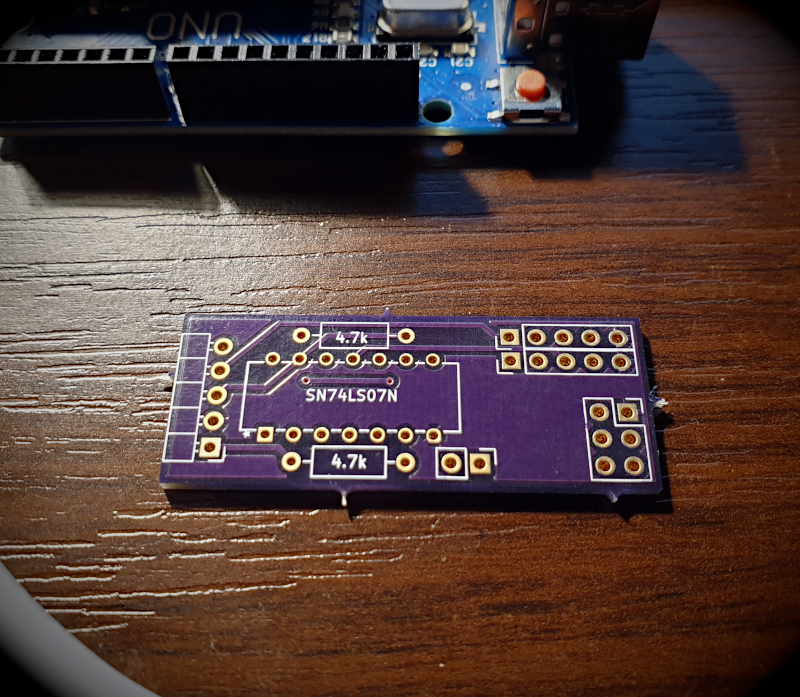 We have a ready, pre-programmed board. Time to put everything together. This extension is not needed when the SDrive is to act as the only device connected to the SIO bus. However, if we want everything to work without any problems, for example by simultaneously connecting a disc drive, we have to make a small circuit, designed by Brend Herale (BigBen) from the German forum Abbuc. The circuit can be assembled “on a spider” or using a universal board, but a more elegant solution is to make a printed circuit board. The circuit is so simple that you can use a method such as thermal transfer of toner and etch it yourself at home. You can also simply order it, for example at OSH Park. So I did, 3 boards cost me 5,80 $. Steve Boswell (known as Mr Robot) has shared his board design.
Necessary parts:
- 74LS07 integrated circuit (e.g. SN74LS07N for 0.98 $)
- 2 x 4.7 kOhm resistors
- 2-pins gold pin header
- 4-pins gold pin header
- jumper
At this stage, the basic skills of soldering of the through-hole elements are required.
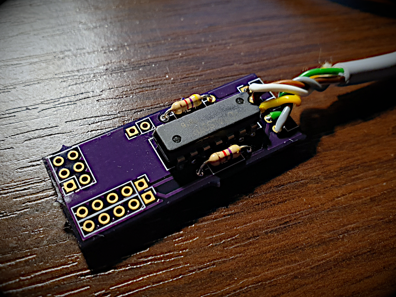
The plate has solder pads marked with numbers that correspond to the pin numbers in the SIO plug. So check the multimeter and write down which colour of cable corresponds to which pin.
Then solder the 2-pin gold pin connector. They must be bent by 90 degrees, otherwise, the board will not fit between the main board and the display.
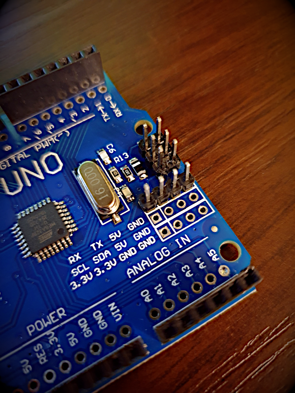
Now you need to prepare a UNO board for the extension assembly. It is necessary to solder the 4-pin connector to the pads marked RX-TX-5V-GND. Sometimes there are three rows and the inscriptions printed a bit lower, so do not make a mistake and do not solder the pins in the middle row! The MrRobot board is adapted to single or double-row leads, but often there are three rows shifted slightly from the original. Then you need to slightly bend the pins to make the board fit.
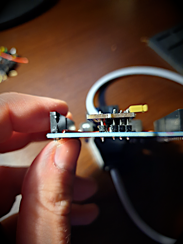
The last thing is to solder the small wire (about 5 cm) to the pads labelled A5. After adjusting the boards to each other, solder the pins permanently.
Jumper is used to choose the power supply method:
- open – you can power the board from an external power supply, or through a USB cable, so you can choose a disk or cassette image BEFORE turning on Atari
- shorted – 5V power supply will be taken from the SIO port
ATTENTION! If the SDrive is connected to Atari, never use an external power supply with the jumper on! You can damage the microcontroller or SIO port in Atari! Do not insert or remove the plug from the SIO port when the SDrive-MAX and/or Atari is on.
Personally, I prefer when the jumper is removed. Using SDrive is much more convenient then.
OK. All that remains to be done is the installation of the display.
4. Preparation of the SD card and software
 You need a microSD card to store files with floppy disk (.ATR, .ATX) or tapes (.CAS) images. I think 4GB should be enough. The unzipped archive with all games takes about 850MB, and utilities about 1GB. There is so much space left (eg for your favorite demos). Where can you find archives with software? E.g. at atarionline.pl. There are updated packages in ZIP format. To use the card on your PC, you will need a USB adapter or universal card reader. Format the SD card by setting it as the FAT32 file system.
 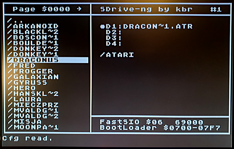 The card should not have multiple partitions so that there are no problems reading it. In the card’s root directory, place the sdrive.atr file. It will allow you to select files without using the touch screen. It will normally be placed in slot D0: and run as the default “diskette”.
5. Have fun 🙂
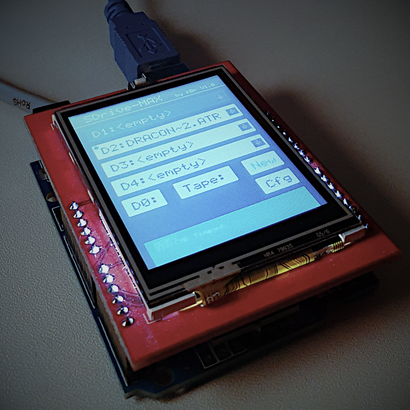
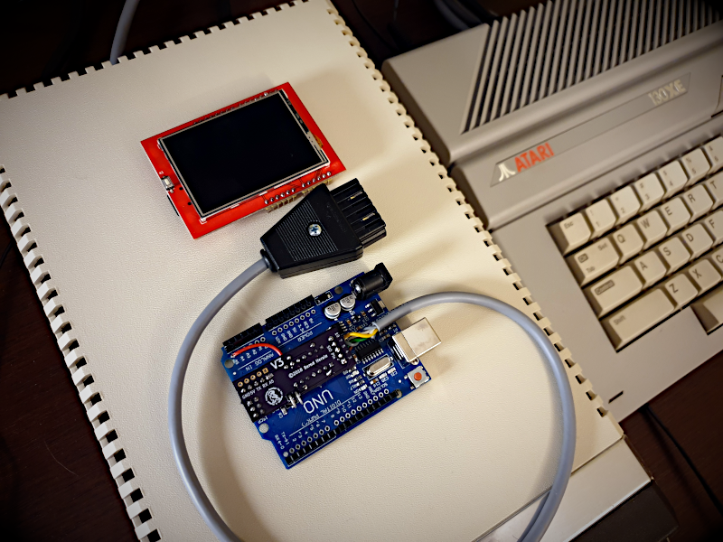
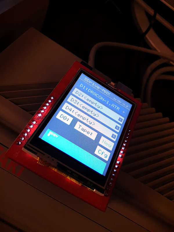
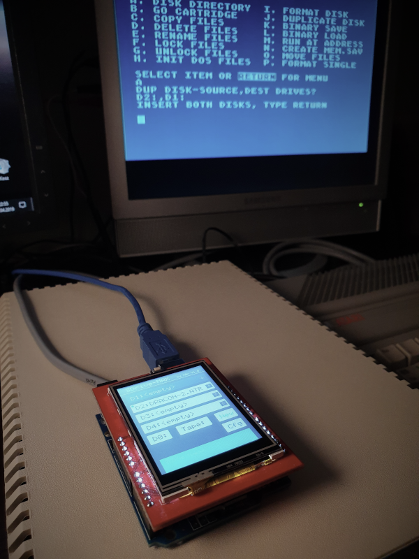
It’s time to connect the SDrive to Atari. First, insert the microSD card, and then connect the power supply to the device, eg from USB (if you have not installed a jumper). At the first start-up, a screen will appear on which you will calibrate the touch screen. Then go to “Cfg” and if you want timings to be accurate with 1050 drives (in ATX file support), select this option. By default, the timings correspond to the Atari 810 disk drive. Click “Save.” Check the slot “D0:”. Now you can turn on Atari with the OPTION key pressed. After loading for a while, you’ll see a screen with the ability to assign ATR images to slots.
As a reminder, if you choose “Tape:” and a file with the extension “.CAS”, then you will load the program just like from a tape recorder, so holding the keys START and OPTION in Atari. This is where the power of the external power setting comes in – you can select the image before enabling Atari.
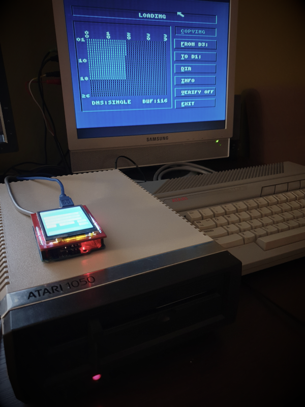
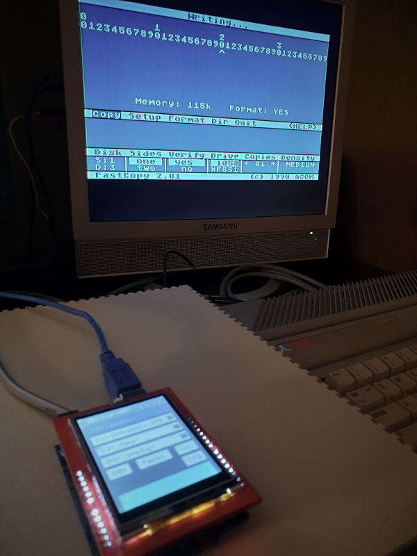
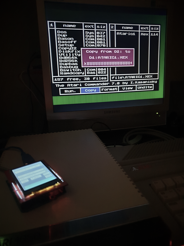
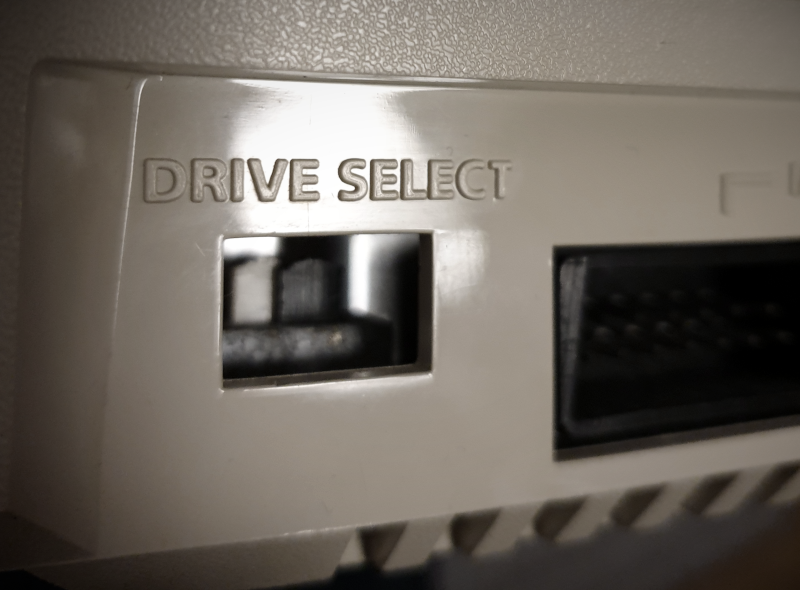 That’s all, your SDrive-MAX is ready 🙂 Now connect the real disk drive, eg Atari 1050 as a D2 device: (set the switches as in the picture) and “insert” AtariDOS II 2.75 into the D1 slot. You will be able to copy the ATR image on a real floppy disk, or backup your floppy disk to a blank image (created with the “New” button). Remember not to use the slot in SDrive that corresponds to the connected physical disk drive number.
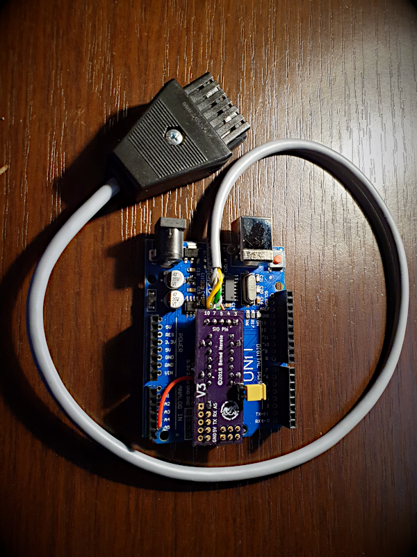
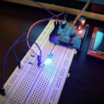
Some photos from my tests:
The whole thing took me about 1 hour, and the cost of creating my own device was about $ 25. (UNO + screen + SIO cable: 82.54 PLN = ~ 21.58 USD, UNO2SIO board: 1.93 USD, other electronic components: <2 USD). The joy of self-assembling SDrive – priceless 🙂
If you have any questions or assembly problems, feel free to write a comment, I will be happy to help you.
Useful links:
- project source code: https://github.com/kbr-net/sdrive-max
- website of the UNO2SIO board author: https://atari8bit.net/projects/hardware/uno2sio/
- discussion on ABBUC forum (in German): http://www.abbuc.de/community/forum/viewtopic.php?f=15&t=9451&start=100
- a lot of information about this modification on AtariAge:
http://atariage.com/forums/topic/275629-sdrive-max-atx-support/page-25#entry4239785 - GERBER files: UNO2SIO.zip
Read more: how to add ‘Power On’ and ‘Activity’ LEDs to your SDrive-MAX
Hi, love this guide, is there any chance you can share the links to the exact items you bought as I am looking to build 10 of these and would like to keep the costs to a minimum. 🙂
it’s best to look for these items on aliexpress