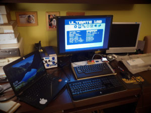
After assembling the Ultimate 1MB, Sophia DVI and Simple Stereo modules, it was time to put all this stuff into the case. It came to my mind a few ideas that I would like to share with you.
1. No need to drill holes in the motherboard!
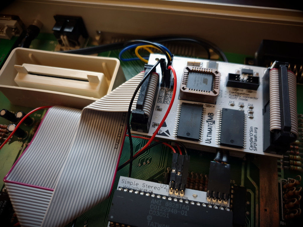
You don’t need to drill holes in the motherboard on the ground fields near the PBI connector.
You can use an existing hole through which you screw the board to the case. However, the problem is that the U1MB will not fit under the keyboard and You will not close the case. Here’s what you need to do:
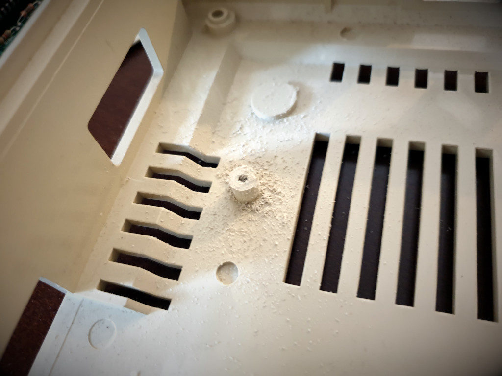
- file off the stand for the mainboard’s fastening screw, a maximum of 3-4 mm should be sufficient, so that the head of the module’s fastening screw can fit under the RF shield
- shorten the plastic distance by about 1/3 (7 mm), so you can screw the module board as low as possible – it will be based on the plastic connector of the tape inserted into the OS ROM socket.

The module will now hold securely and low enough to fit calmly under the keyboard and you can easily close the case. Lay the keyboard tape in such a way that it doesn’t overlap the Pokeys.
2. Hole in housing for DVI connector
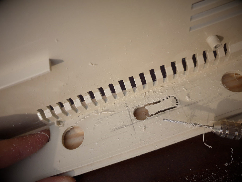
If you have decided to solder the DVI board to the motherboard in place of the modulator, you must cut a hole in the housing through which the plug and fastening screws will pass:
- stroke the outline of the socket with a pencil
- using the ruler draw the cut-out lines, give a small margin, make sure that the lines are perfectly parallel to the edges of the case 🙂
- drill a dozen or so small holes inside the contour
- patiently, use the file to align the edges of the hole to the drawn lines
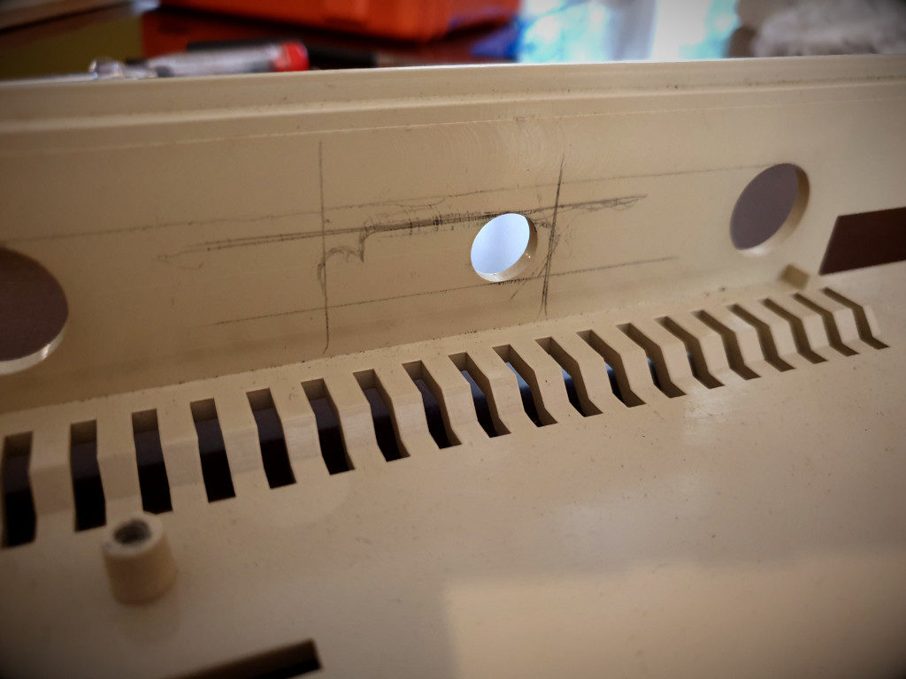
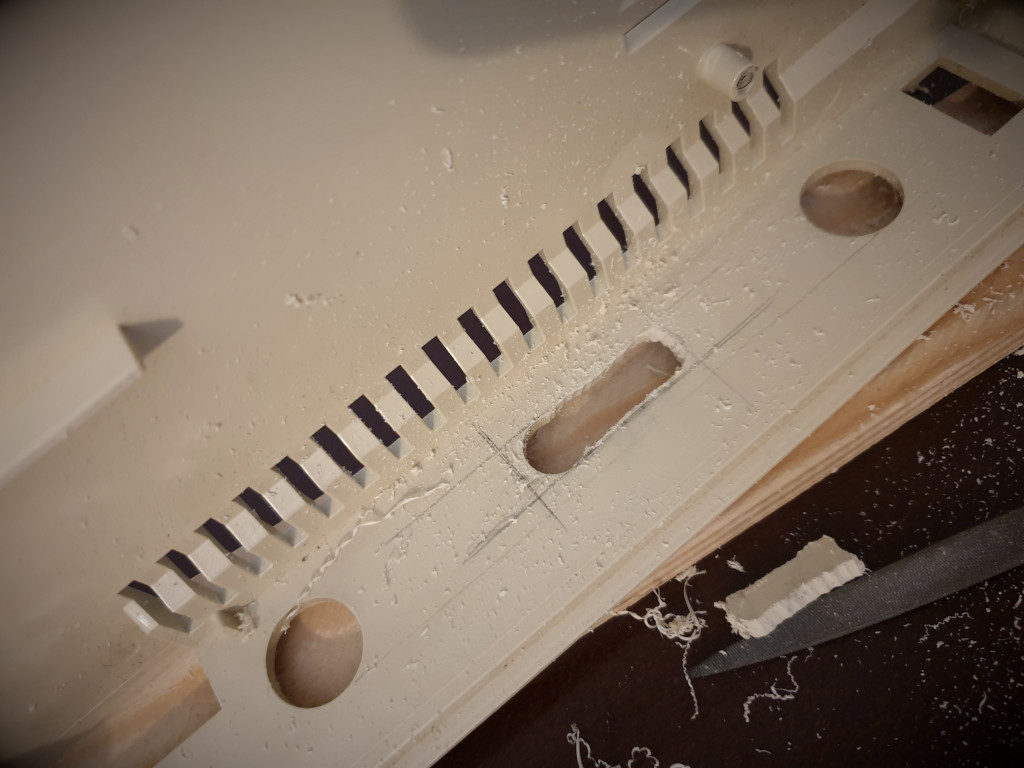
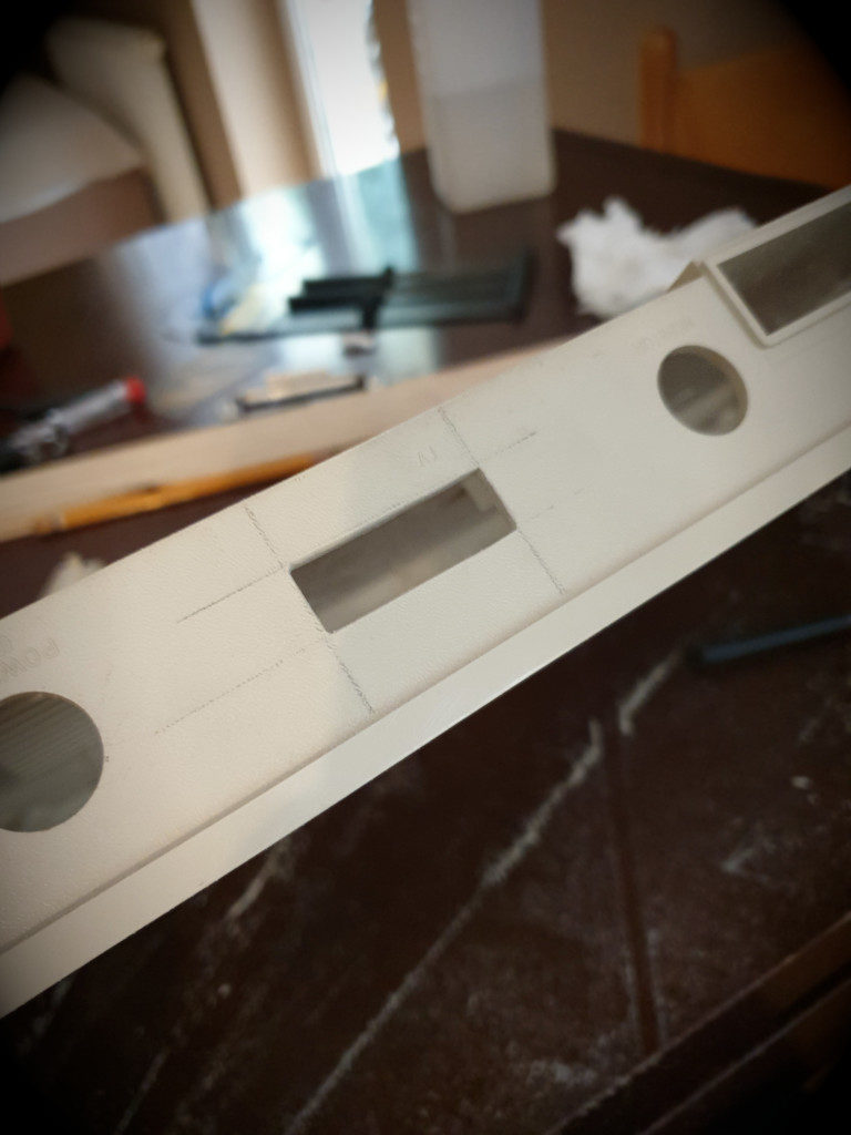
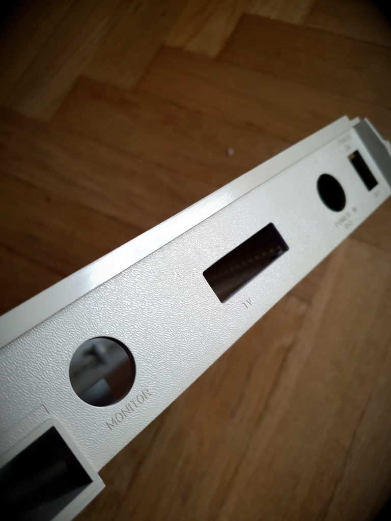
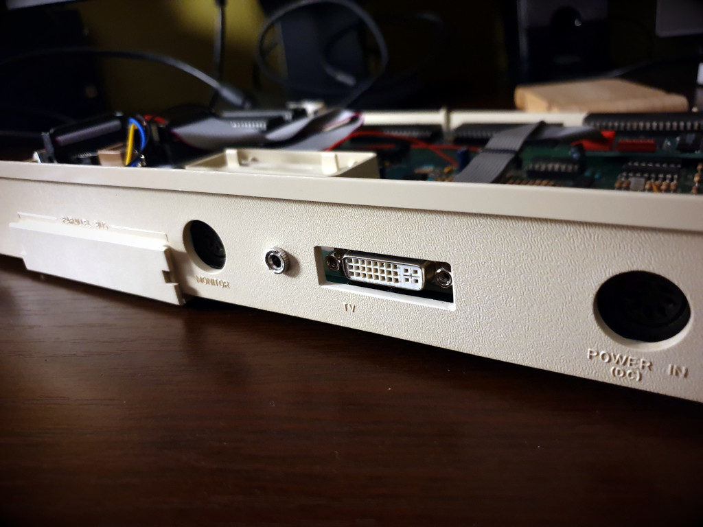
Grinding requires a lot of patience and precision, and I am very satisfied with the final result:
after cleaning the housing
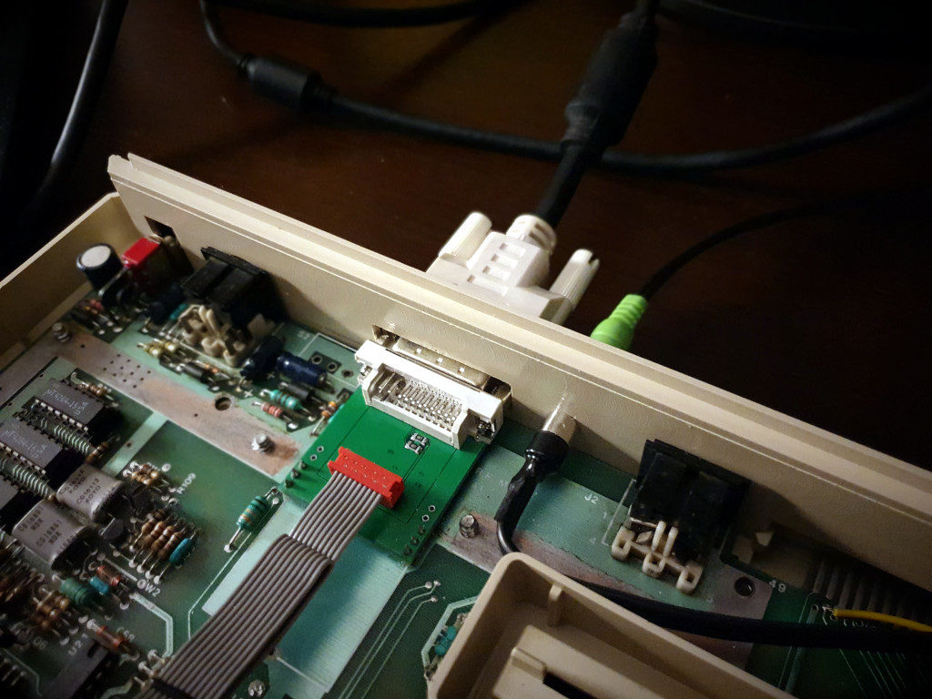
– view from the inside
It’s ready. I also decided to replace two cinches (RCA) soldered to the audio cable with a stereo jack. Less drilling, more space on the rear panel, it looks nicer.
3. Replacing the capacitor next to the Pokey chip
Next to the Pokey chip is an electrolytic capacitor C98, which interferes with the installation of the Stereo board. To be able to mount it, an additional DIL socket had to be placed underneath it. This capacitor on my motherboard was already a bit corroded, so I decided to replace it. However, I inserted the new one horizontally, so I could take out the unnecessary socket. It also turned out that the removed old capacitor had 12.8 uF instead of 10, which exceeds 10% tolerance. When replacing, pay attention to the correct polarity!
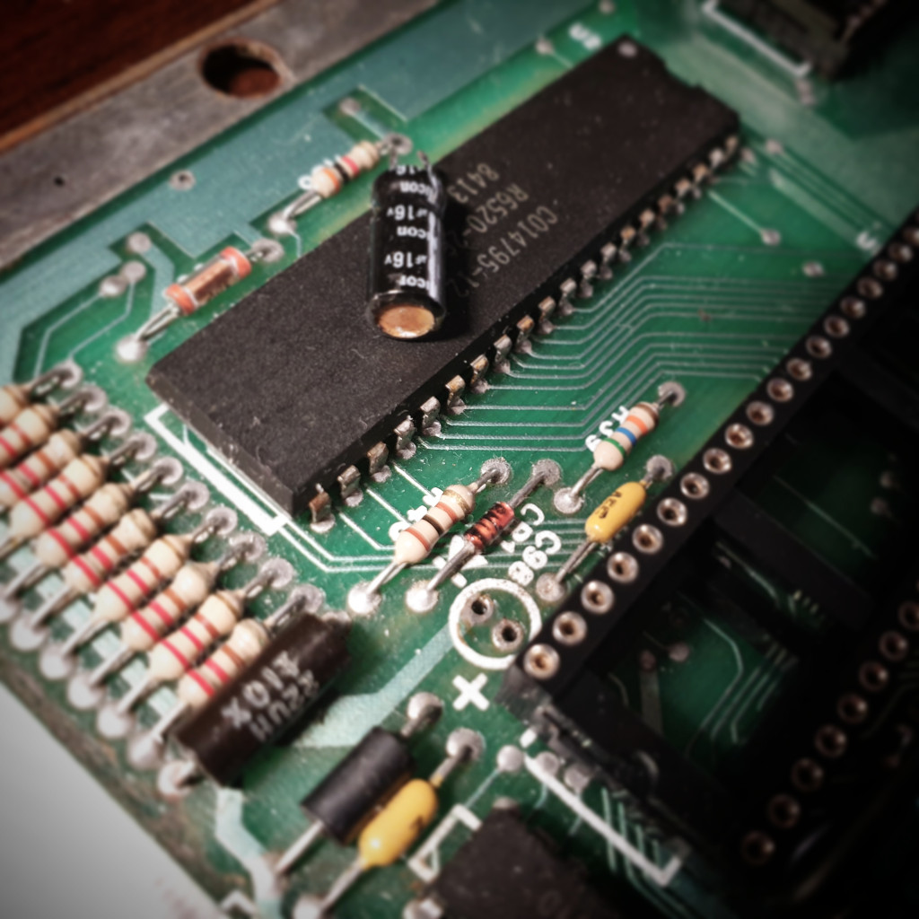
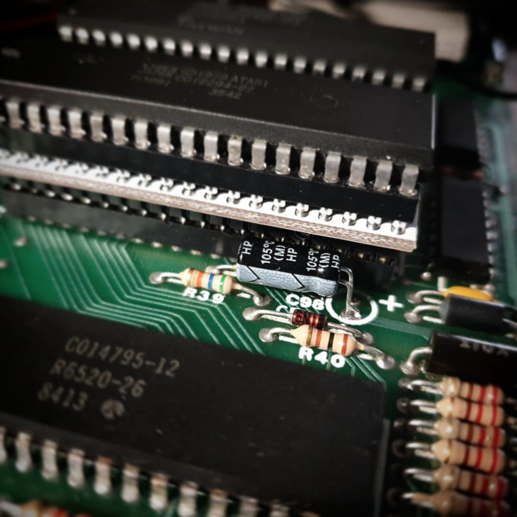
When replacing, pay attention to the correct polarity!