
I’ve been thinking about expanding my Atari for a long time, but it took me a while to complete all the necessary elements. Here’s a report from the front line. I don’t recommend to do it if you’ve never had a soldering iron in your hand before. Well, it’s time to create a real 8-bit monster!
First of all:
SOME EXPERIENCE IN SOLDERING IS REQUIRED. IN PARTICULAR, YOU WILL NEED TO DESOLDER SEVERAL ATARI INTEGRATED CIRCUITS. YOU ACCEPT RISK AND YOU DO IT AT YOUR OWN RESPONSIBILITY.
1. Extensions to be installed
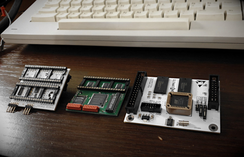
Ultimate 1MB – I don’t know if it’s necessary to introduce it. It’s basically a ‘must-have’ for anyone who wants to play Atari every day, not just collect and keep it in a display case (or worse, in the basement :)) In addition to 1MB of memory, we get the ability to program and select several ROMs with OS and Basic, loader for SIDE2 cartridge, built-in SpartaDOS X, real-time clock and many other features. More on this subject on the manufacturer’s website, and the author’s of the improved firmware.
Sophia rev. C DVI – a brilliant module that mounts under the GTIA chip. It retrieves data directly from it, and generates a digital image in the DVI standard itself, completely bypassing the Atari video circuit. As we know, without modifications (such as S-Video Mod or UAV) Atari does not generate the most beautiful (to put it mildly) image on modern LCD monitors 🙂 Sophia gives you the perfect digital picture quality with a resolution of 1280×1024. I have to admit that it looks great. Other resolutions for 16: 9 or 16:10 wide screens are also possible, but to maintain the correct aspect ratio you need to ask the author to program the proper firmware for the target resolution. More details and the possibility of ordering the module can be found on the AtariAge forum.
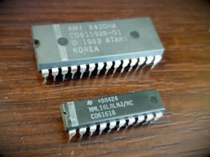
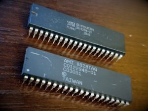
Simple Stereo V2 – a simple board that allows you to add a second Pokey chip, so you get stereo sound and 8 channels. There are many new demos and several games (including some converted old ones) that can really rock out with this extension 😉 Unfortunately, you will have to get Pokey from somewhere – from another completely damaged motherboard or e.g. from eBay. Fortunately, (soon I hope) an implementation of four Pokeys in FPGA will be available, so you will not have to cannibalize boards that can be resurrected in 99% of cases 🙂
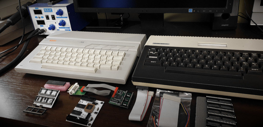
2. Dilemma: 130XE or 800XL
I wondered for a long time which of the two Atari models I want to upgrade. My 130 is in perfect visual condition: the lack of yellowing, abrasions or cracks makes it pleasing to the eye. And because it has 128 KB of RAM, I naturally use it most often. On the other hand, 800XL: a cult model, a little weary with age, de-rusted and cleaned. Probably kept somewhere in a cold, wet basement (judging by the condition of the RF shield and the smell of mushrooms). However, it has an indelible keyboard and more space on the back for additional connectors.
Why did I decide to choose XL?
- most chips are factory socketed, so all that remains is to desolder OS ROM and MMU – less work and less risk of something going wrong
- completely dilapidated modulator, which wouldn’t hurt to remove and replace it with DVI socket
- I want to keep the original look of the 130 without drilling anything into its housing
3. Let’s begin: desoldering the proper chips
In fact, I started impatiently by mounting a stereo module, wanting to hear two Pokey’s playing. However, I recommend starting by desoldering the appropriate circuits and soldering the sockets in their place. The module will not disturb during frequent turning of the motherboard, nor do we risk that we break something at the same time.
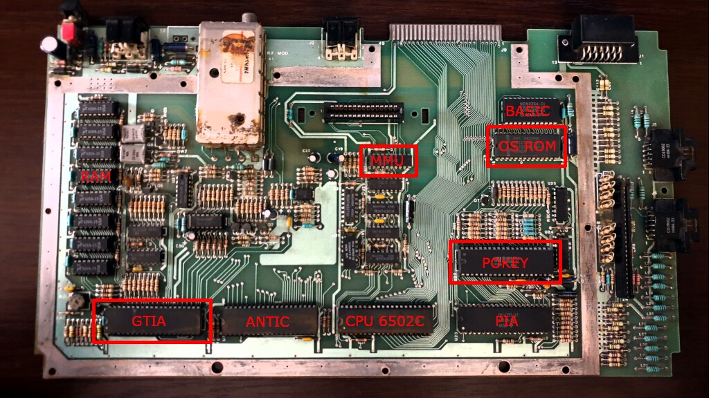
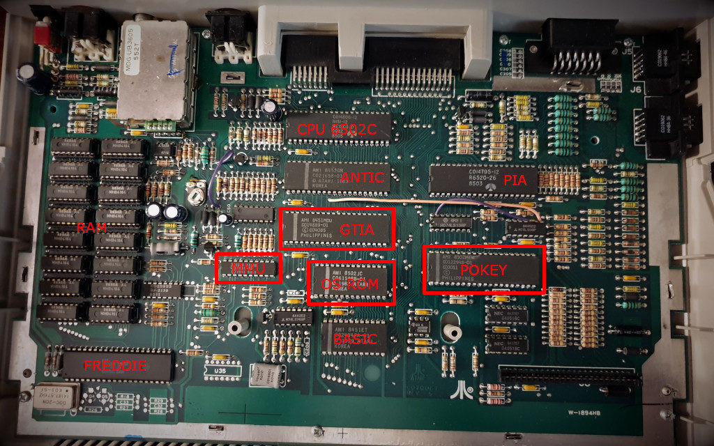
Locate the following ICs: Pokey, GTIA, OS ROM and MMU. In the picture below, you will find the places where they are located on the motherboard:
In the case of my Atari 800XL, it was enough to desolder the OS ROM and MMU. There are also models where almost all the chips are factory-mounted on sockets, so we have downhill. Unfortunately, in the 65 XE, 130XE and 800XE models, most often they are all soldered directly to the motherboard. This is the most difficult part of the whole upgrade. If you have never desoldered DIP40 chips, don’t do it yourself. It is better to pay these several bucks to an experienced electronics than to destroy your equipment. However, if you are determined to do it yourself, at least practice on some old PC network adapters or something like that.
- it is very easy to peel off the pad or track if you overheat the soldering spot
- using only a soldering iron, a tin pump and a copper braid is a torment, not only for beginner electronics 🙂
- be especially careful with legs connected to ground fields, they require a greater heat transfer, tin connection is also on the other side of the board (from the top)
- do not tug and do not pull the IC out if it does not go out – somewhere a little bit of tin still holds somewhere – check with a flat screwdriver, whether the legs move in the holes, if not – “peel off” the leg from the wall of the hole and slide it with the soldering iron to the centre, clean this place thoroughly with a braid
- it happens that even desoldering guns do not suck out the whole tin from the hole, solder a little fresh tin – then it should be easier to suck out everything
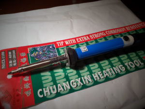
Ideally, have a temperature-controlled soldering station and desoldering attachment (desoldering gun). I have a cheap Chinese “desoldering iron” (a combination of a soldering iron and a pump in one) and I have to admit that it does quite well. Remember, even expensive high-end equipment can suck in a pad with tin if it is not used properly.
4. Inserting the sockets
Pads after desoldered ICs are elegantly cleaned from the remains of tin with copper braid. I have additionally cleaned them with a contact cleaner which removes oxides (rust) and other dirt that may affect the deterioration of contact. Finally, I degrease the surface with isopropyl alcohol. It is necessary to check under a magnifying glass whether everything is OK and if any pad has not evaporated 🙂 The places prepared in this way are ready for the insertion of the sockets.
We need a narrow 20-pin DIP socket and a wide 28-pin one. If we additionally desolder Pokey and GTIA – then we need two more wide 40-pin DIP, of course. I didn’t have a 28-pin one, so I cut a nicely larger one to the right size. When placing the sockets in the holes, make sure that the metal plates do not pop out. If this happened, most likely there was a little bit of tin left in the hole, which does not allow one of the legs of the socket to enter freely. There is no more philosophy in soldering the sockets. We take care of the timing of the soldering tip to avoid melting the plastic, as well as the cold joints that may occur.
Insert previously desoldered ICs, possibly clearing their legs of tin residues. If necessary, gently straighten with pliers. Now turn on ATARI. If we see the READY prompt, it means that everything went well. If we see a black or red screen instead, we have a connection problem somewhere. Red usually indicates a problem with U5. Do not panic. Turn off ATARI, remove the OS ROM, check the connection between the socket plates and the vias to which the paths from the pads lead with a multimeter. The circuit diagrams of our Atari will be useful at this point. Also, check if any dirt has fallen into the slots, being able to block the connection. Clean the IC’s feet with a contact cleaner.
5. Mounting Simple Stereo V2
OK. The most laborious and critical stage is behind us. The ICs sit in sockets, ATARI starts up, it’s time to install our extensions 🙂
Let’s start by removing the Pokey from the socket, gently levering it from both sides with a flathead screwdriver. Thoroughly clean the contacts of the oxides.
The second Pokey chip was obtained from a totally destroyed 800XE board, which was definitely not suitable for repair. This board had broken and torn connectors and damaged tracks. I bought it for about 30 PLN (~7.5 USD) as a spare parts reservoir, hoping that the integrated circuits still work. I cleaned out the desoldered Pokey from the leftovers of tin and washed it in IPA.
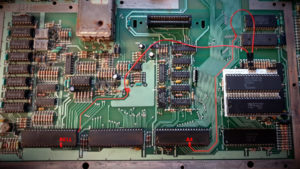
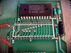
Time to prepare cables for BELL and A4 signals. I took the ready-made cable with connectors and cut it in about 1/4 of its length. The BELL signal comes from the GTIA foot 15, while the A4 signal comes from the 13th CPU foot. You can solder the cables directly to the legs, but in my opinion, it is much better to find convenient places on the motherboard. I take the BELL signal from the C23 capacitor’s leg, and the A4 signal from the via next to the OS ROM circuit. I marked the exact place of soldering on the picture below:
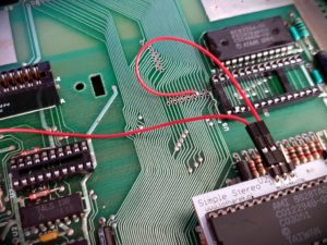
We will now install the Simple Stereo module. First insert both Pokey chips (pay attention to the chip orientation!) and then install the board in the slot. Next to the U22 socket there is a C98 capacitor. It will interfere with the installation, so you need to use an additional socket, which you insert between the Stereo module and the one on the board. Thanks to this, the module will be raised and the capacitor will be underneath it. Finally, connect the soldered cables. The last pin in the module is used to turn on/off the stereo. Connecting it to the ground will deactivate the module. For the moment we leave this pin disconnected. Connect it later to the U1MB card.
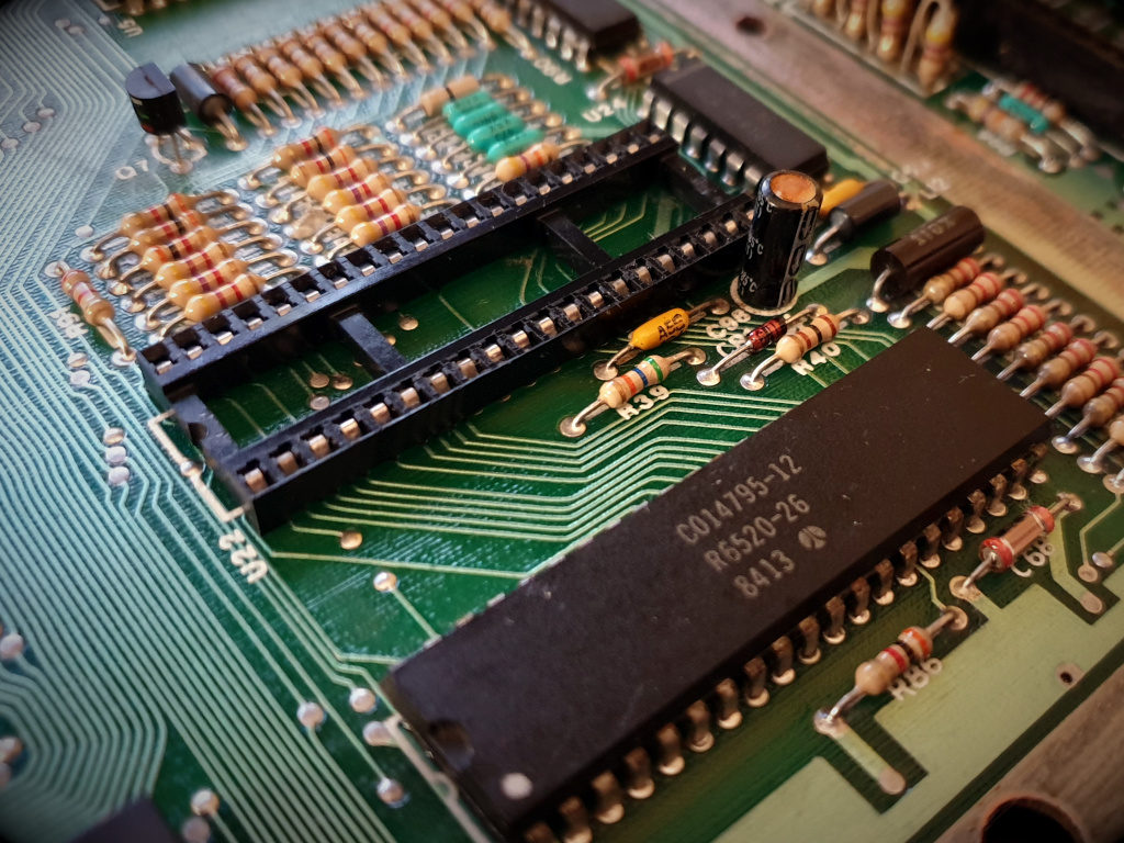
Pokey’s socket. When the IC is removed, the contacts are cleaned of oxides. 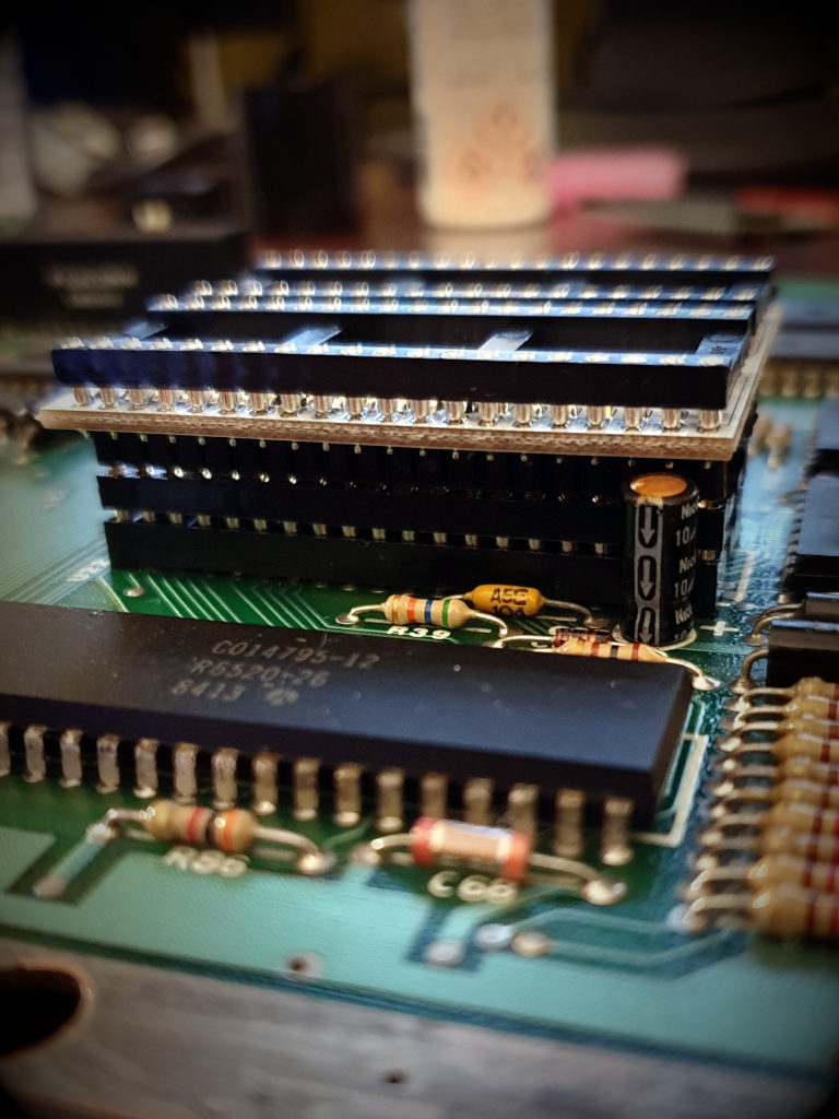
A interfering capacitor, we put on an additional socket. 
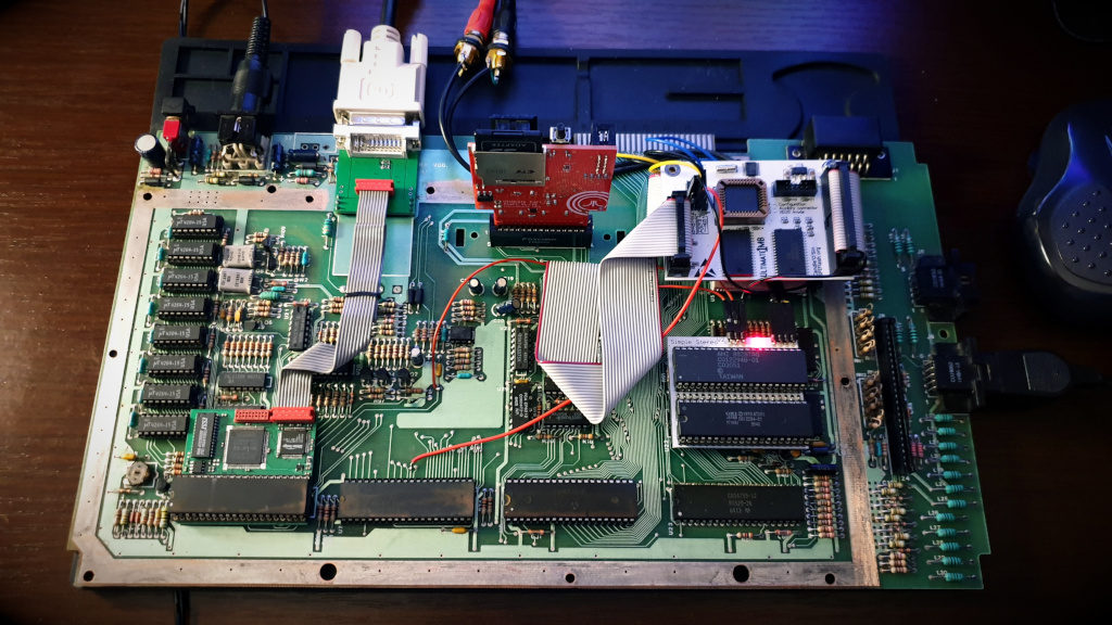
Soldering points. LED lights up – stereo active 🙂
We’re launching ATARI. The red LED on the module should light up. This means that the Stereo is active. You should also check with e.g. the SysInfo program whether the module is detected. All you have to do is make a cable to lead out the left and right channels. I used about 30cm of two-core shielded audio cable. The order of the leads is as follows: LEFT – GND – GND – RIGHT.
The stereo mod is ready.
6. Mounting Sophia DVI
First of all, we have to think about whether we should leave or dismantle the modulator. The DVI plug fits quietly over it, so you can still have the old antenna output. However, the removal of the modulator has its advantages: it reduces the level of interference in the video circuit, improving the quality of the image on the standard “Monitor” output.
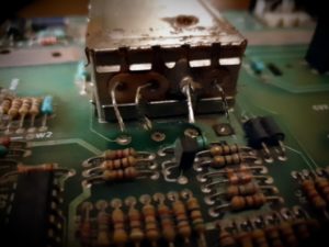
In my model the modulator was already heavily affected by rust, and the image from the antenna output was heavily snowed, so there was no point in holding it. I don’t think anybody uses this output anymore. Even if he loves retro-gaming on a real TV/CRT monitor, he most probably uses SCART or SVIDEO connector. So I decided to desolder it making room for a decent DVI socket attachment:
- The connection of the modulator to the board is soldered out simply: you heat the wire at the same time with the soldering iron and as soon as the tin melts, pull it up gently. You better use the pliers for this or you’ll burn yourself.
- Attachment to the modulator from underneath: suck as much tin as possible out of the attachments so that they can be straightened with pliers and can pass through the holes.
- When heating with a soldering iron on one side, gently lift the modulator with a screwdriver or tweezer on the other side. By gently but with a bit of force, the modulator should exit.
Honestly, I sweated a lot on this operation, but it was worth it. Under the modulator there was a large layer of rust, you can see that moisture was gathering there. All that remains is to clean the boardwith e.g. isopropyl alcohol and to remove the remains of tin with a braid.
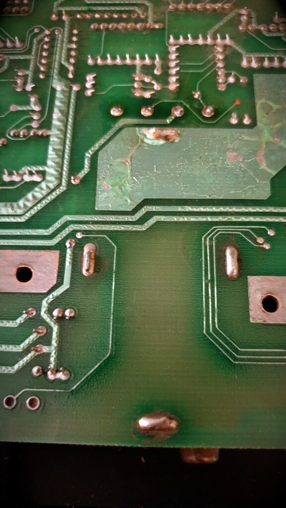
Suction the tin and straighten the plates. 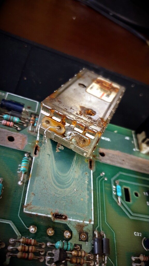
Dirt and rust. What was going on here o_O? 
Cleaned empty space
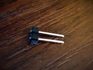
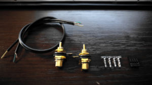
We have attached pinheads to the module which can now be soldered to the places of mounting the modulator, and the socket board itself has holes exactly in the right places. I additionally soldered to the front hole a “stand” with two pins so that the plug does not hang in the air. We risk breaking the board when connecting/disconnecting the DVI cable, which is heavy enough to give a leverage effect on the board.
I recommend to solder the stand first, insert the mounting pins, insert the board with the socket, fit the holes, and then solder the board from the top to the pins. Thanks to this, nothing will move and it will fit nicely to each other. At the end we solder the pins from the bottom to the motherboard.
Installation of Sophia should not be a problem. Pull out the GTIA from the socket on the motherboard and replace it with a module. Then insert the GTIA into the socket on the module, just remembering to insert it in the right direction (as it was before). Connect the flat cable to the connector on the right and to the DVI connector board.
Phew, it was worth it 🙂 The picture is like a dream. Malicious people claim that it looks like an emulator on a full screen. Ehhhhhh.
I only had to switch my NEC into 4:3 mode to keep the image from being stretched and choose a profile with a slightly colder color temperature.
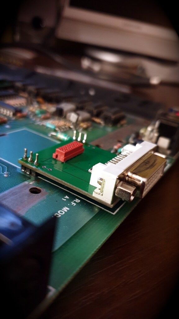
Installing the DVI plug into the motherboard 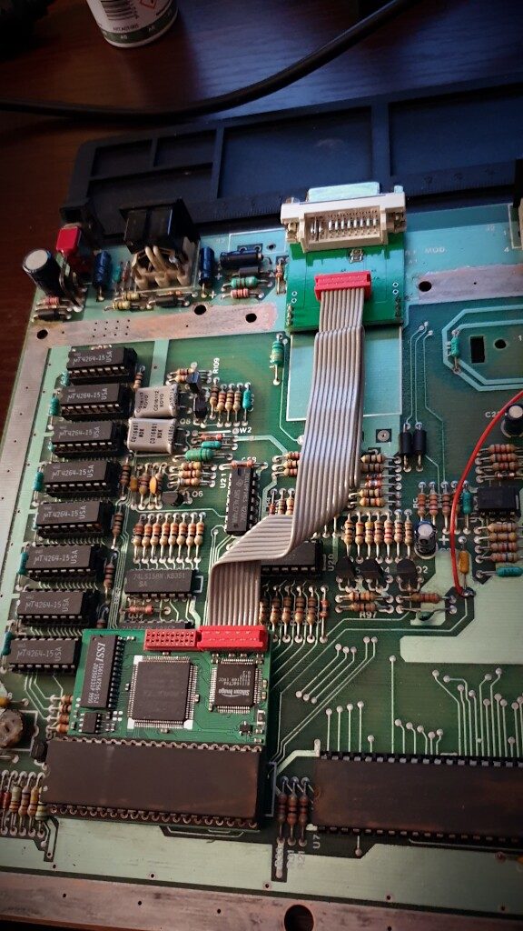
Signal tape connection 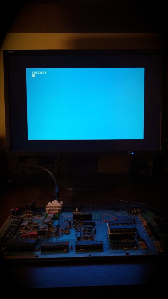
Switch on and ready to go 🙂
7. Ultimate 1MB – finally!
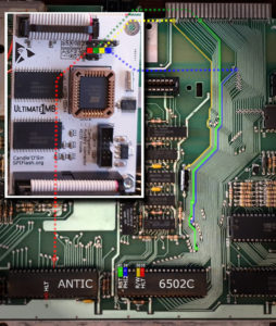
The time has come to install the most important extension, the Ulitmate 1MB. We start by finding four signals on the board: PHI2, R/W, RST and HLT. These signals are connected to the CPU. Of course, you can solder the cables directly to the CPU feet, but I am not a fan of such a solution. Instead, we are looking for convenient places on the board where you can nicely solder the wires. Such places are e.g. vias, through which we can easily pass the cable and solder it elegantly on the other side of the board. The picture shows places recommended by the author of the module – Candle’O’Sin. He also recommends cutting the cables connecting the module with the motherboard as much as possible.
To fix the module, you need to drill one or two holes in the mainboard. The holes should be 3mm in diameter. Of course, the holes must be in an empty space between the paths 😉 In Atari 800XL the space above the OS ROM chip is a good place.
We’re fixing the signal tapes now. We put them in the sockets instead of OS ROM and MMU chips. The most important thing is to make sure that they are connected in the right direction. The red bar marking 1 must be located on the left side (where there is a notch on the socket). Now I had to do a little twisting to make the tapes look elegant in the case and at the same time to make the plugs well oriented towards the sockets on the module. It is impossible to connect to the board the other way round. In the pictures below you can see how to bend the tapes.
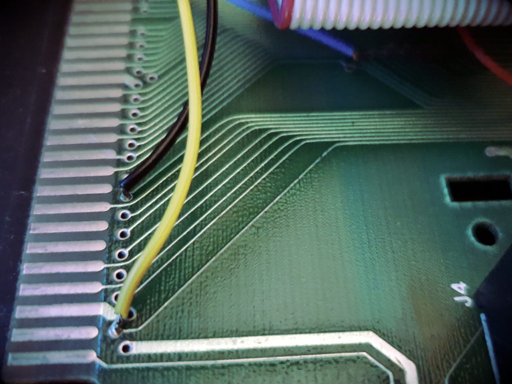
Exemplary connection of PHI2, R / W and RST signals 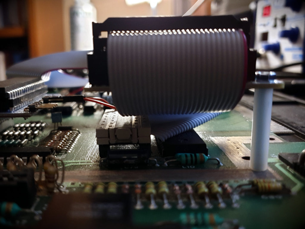
Fastening screw and connection to the OS ROM socket 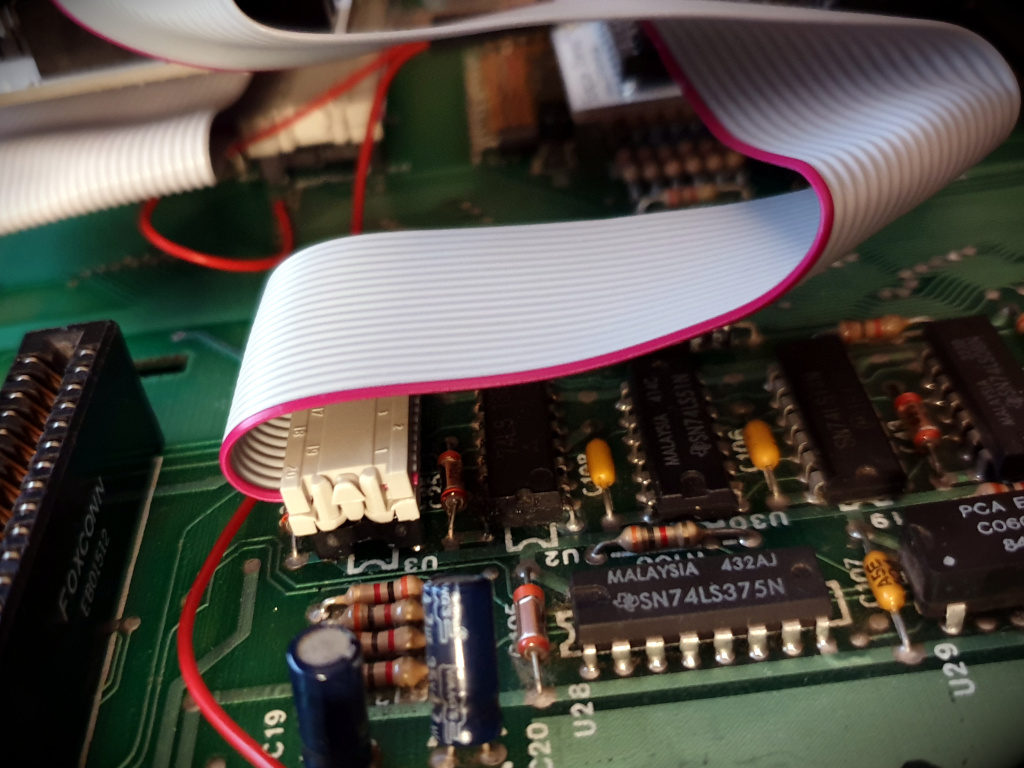
Connection to the MMU socket
When everything is in place, we put the plastic spacers on the screws and screw the U1MB from above. Connect the plug with the soldered wires. It remains to connect the stereo module control to the pin marked S0.
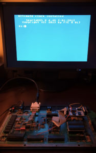
After turning on ATARI, we should hear a characteristic clattering, and after a while see the screen with the loaded SpartaDOS system. If this is the case, then most likely everything works as it should 🙂 Pressing the HELP key while switching on will take you to the extension configuration screen. Set the memory extension mode (1088k RAMBO), decide whether to start SpartaDOS, set the standard XL system for now, activate the Stereo module, and finally set the real-time clock. Save the settings by pressing the S button.
It’s ready! We should now test the extended memory with one of the dedicated diagnostic programs such as the eXtended RAM Test.
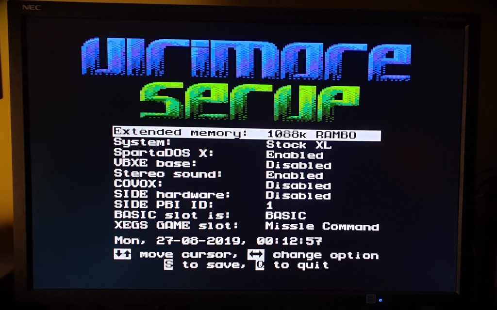
By pressing the HELP, we’ll enter to the settings screen 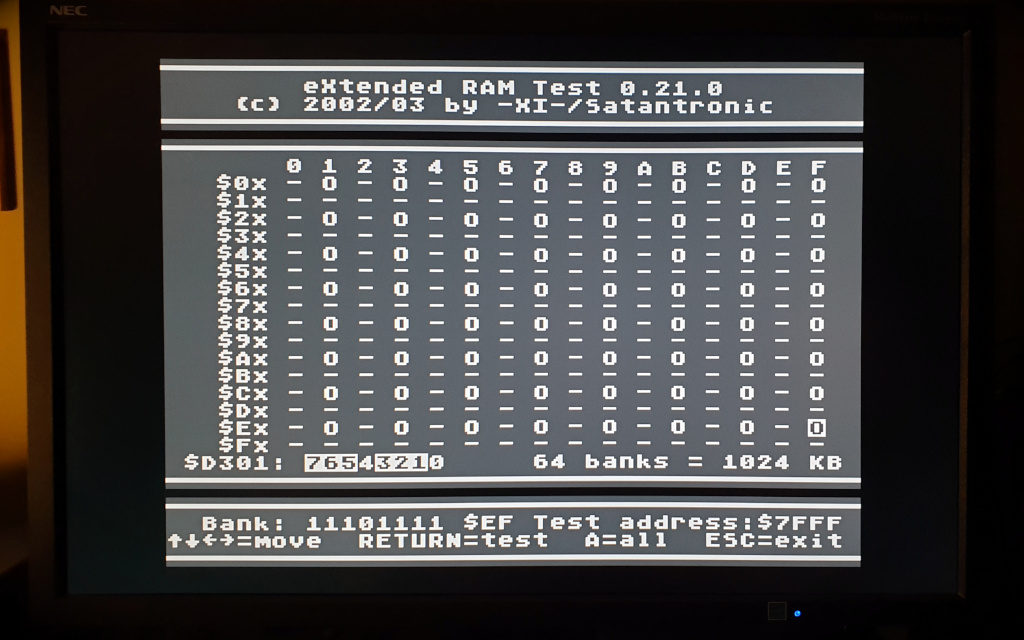
XRT is a great memory
testing tool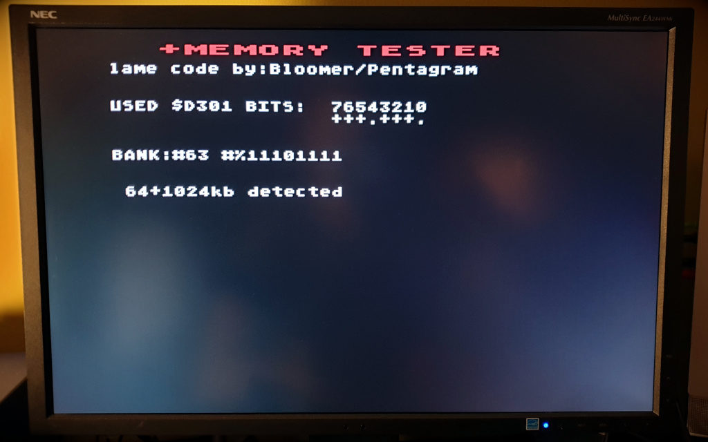
Additional 1024kB of memory detected and tested
8. Updating with the latest firmware

In fact, you can already enjoy the installed extensions. But it is really worth to install the latest firmware by Johnatan Halliday – also known as FlashJazzCat.
One of the most convenient ways to do this is to use a Sio2SD or SDrive-MAX device. Download the latest firmware version from the author’s website, extract and copy the file FIRMWARE.ATR to the SD card. We “mount” it in our disk drive emulator as a D1 disk. Run the UFLASH.XEX file from SprataDOS.
I decided to replace all flash memory content with a new batch. So all slots with systems and basic will be overwritten. So I select the main ST39SF040 slot and choose ULTIMATE.ROM file. The whole flashing process takes a dozen or so minutes. It is also a good test of stability of our system. Unfortunately, if during Atari update it crashes or restarts, our U1MB module will be ‘bricked’. You will need to remove the flash memory and program it ‘manually’ in a programmer such as TL866II+. Especially owners of Atari 1200XL should read the instructions on how to avoid trouble.
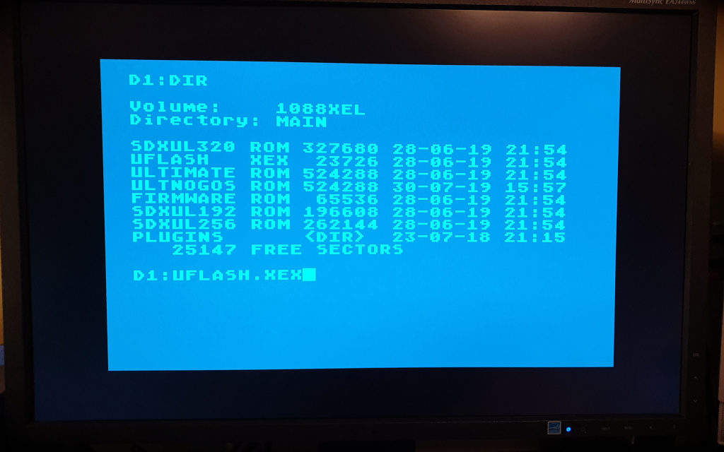
Loading the flash program 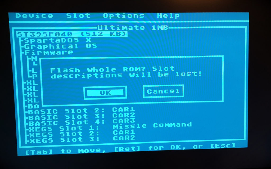
Choose to update
the whole ROM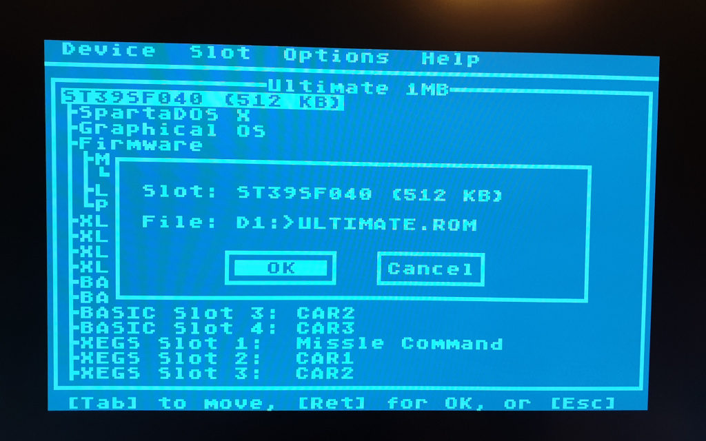
Choose the file
with the ROM image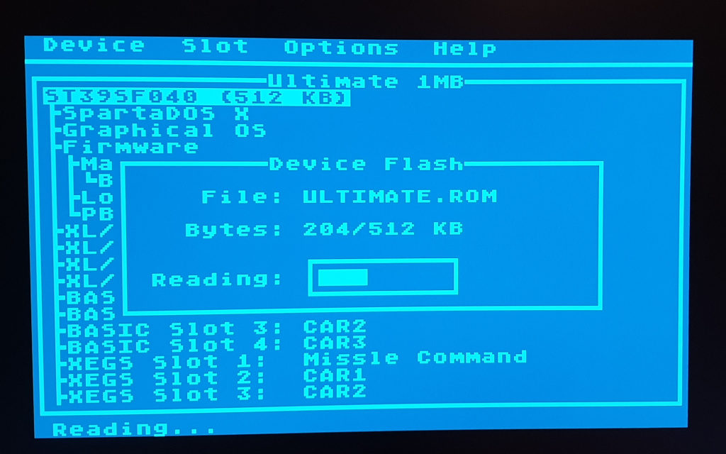
Reading…. 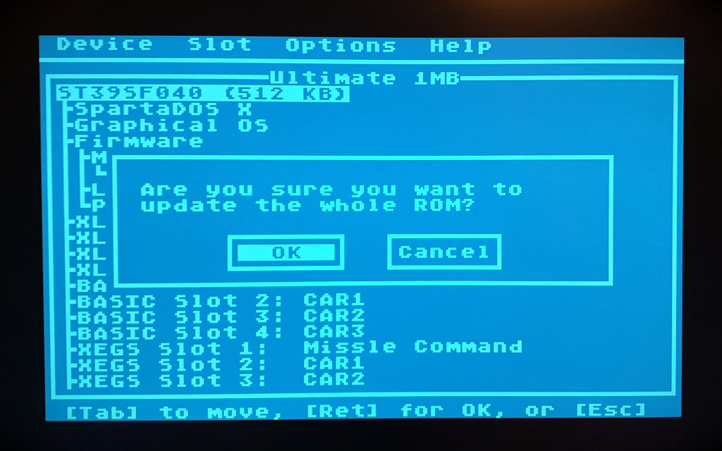
Yes, I’m sure! 🙂 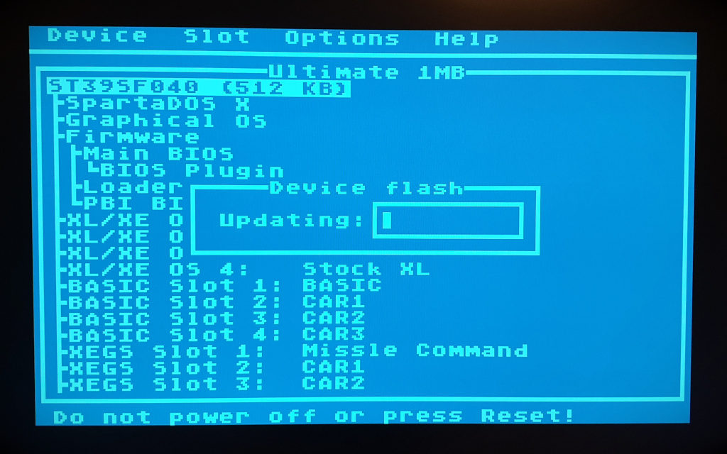
Nervous waiting…
The update process will be followed by verification. A moment later we should see the window “Completed successfully”. After restarting and pressing the HELP key, we will see a new configuration program.
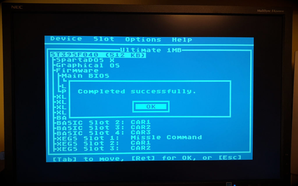
We did it! 🙂 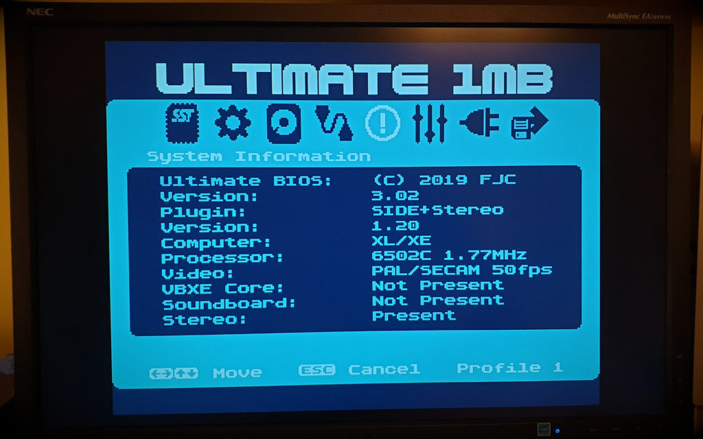
After the restart we have a new configurator
It’s over! I must say that the extensions really breathed new life into my Atari. Perfect picture on LCD monitor, stereo and additional 1024kB of memory, which should be enough for everyone 😉 Now it will be a basic machine to play every day and to take to the party. Finally you will be able to watch the latest demos on real hardware.
The assembly of all the extensions will certainly take a few nice hours. It took me four evenings with breaks. All that remains is to adjust the chassis: cut out the space for the DVI socket and drill holes for the stereo cinches.
OKAY. That’s all Folks! If the above article is useful for you, buy me a beer 🙂 Go ahead and write in the commentary if you have a problem. I’d be happy to help. I can also help you with the installation of extensions if necessary – just write an e-mail.
In the next article, I will present how to install a motherboard with extensions in a housing.
Useful links:
- Simple Stereo V2: https://lotharek.pl/productdetail.php?id=200
- Ultimate 1MB: https://lotharek.pl/productdetail.php?id=56
- Firmware for U1MB: https://atari8.co.uk/firmware/ultimate-1mb/
- Sophia rev.C DVI: https://atariage.com/forums/topic/274004-sophia-revc-dvi-board/
- How to build SDrive-MAX yourself: http://en.devzine.pl/2019/05/08/how-to-build-sdrive-max/
- eXtended RAM Test: https://satantronic.com/files/8bit/tools/XRAM0220.XEX
- SpartaDOS X documentation: http://sdx.atari8.info/index.php?show=en_docs
- Atari schematic diagrams: http://www.jsobola.atari8.info/dereatari/schematy.htm
where do you buy the ic sockets from?
just received a 1mb ultimate up grade and am looking for a mmu and os rom socket.
thank you
To tell you the truth, I don’t remember, I just have it in my desk and if I need something, I look for it and I have it 🙂 I buy electronic parts mainly on Allegro (“Polish ebay”) or bigger quantities on AliExpress. DIP sockets should be easily accessible in any electronic parts store like Mouser, Digi-Key or Farnell i.e.:
– DIP28 socket
– Narrow DIP20 socket